

Capturing the Digital Dividend
Background:
With the evolution of modern digital television systems, broadcasters can transmit several digital television channels in the radio-frequency spectrum used previously only by one analogue channel. Therefore, during the transition from analogue to digital terrestrial television, large amounts of radio frequency spectrum are freed for more services and technology. Digital dividend refers to this resultant increase in opportunities to deliver more services. While analogue switch-off can certainly deliver dividends, are there pitfalls leading to losses in the process? This case study is a brief example of how issues of digital dividend were investigated carefully for potential deficits.
Client’s Challenge:
Our client was one of the largest commercial TV networks in the region. After transitioning to digital TV, the regulatory authorities proposed the release of 700 MHz band (698-806 MHz) to mobile services using LTE. This proposal for LTE complied with the Asia Pacific Telecom (APT) band plan. It uses the conventional duplex, which implies that the uplink, from the LTE user equipment (UE) to Base station, is located in the lower part of the band (703-748 MHz); while the downlink, from the base station to UE, is located in the upper part of the band (758-803 MHz). Our client was concerned about the potential interference Digital TV would be subjected from a future 700 MHz LTE allocation.
We helped our client by conducting a detailed study the compatibility of 700 Mhz LTE allocation on the digital TV network, as for our client’s case an ISDB-T network.
The Approach:
We designed the study to answer our client’s concerns and also devise mitigation strategies to help them overcome potential challenges.
There are 2 main parts to the study:-
- Investigation of the potential interference from the LTE UE (uplink) into the ISDB-T network.
- Investigation of the potential interference from the LTE base stations (downlink) into the ISDB-T network.
We utilized 2 different methods in the study:-
- Minimal Coupling Loss method (MCL) uses simplified calculations to assess the interference and ways of mitigation. The basis of this method is a set of defined reference cases where ISDB-T reception should function in the presence of the 700 MHz LTE signals. We combined our calculations with the use of a free space propagation model. MCL studies were conducted for both uplink and downlink. From the results created, we will then design potential mitigation actions and study their efficacy with similar methods.
- PROGIRA® plan simulations to evaluate the impact of LTE downlink interference without any reduction of interference (mitigation). With PROGIRA plan, we can show areas where (geographical), as well as who (population) will have their DTT network interfered by the LTE downlink.
Technicalities:
MCL Methods
MCL methods were utilized in this study as it is deterministic and relatively easy to apply. It is instrumental in determining out of band emission (OOB ) limits for an LTE user terminal (UE), interference from downlink in the 700 Mhz band, and detailed investigations on mitigation strategies of interference. We identified 5 objectives for performing MCL. One, to establish the minimum or critical distance. Two, to derive the OOB power for APT LTE mobile and DTT receiver selectivity (ACS) requirements. Three, to calculate the impact of receiver overload. Four, to calculate the impact of additional filtering on interference. Lastly, the results derived from achieving the objectives mentioned above, help us understand the mitigation efforts required to avoid interference. We used the Free-Space Model for MCL studies.
PROGIRA® plan Simulations
There were a few considerations when performing simulations with PROGIRA® plan. Firstly, we needed information on existing mobile base stations in the area. Secondly, we created various scenarios from different reception characteristics, such as rooftop, rooftop with booster, communal antenna, indoor, indoor with booster or mobile. Lastly, we needed to define interference due to ISDB-T receiver overload, and areas where protection ratios (PR) were not fulfilled.
Results:
The extensive studies revealed that the impact of interference is significant. The impact is particularly critical for cases where antenna amplifiers were used in DTT reception.
The calculations performed in the planning software for the LTE downlink demonstrated that the interference could potentially affect between 10 and 40% of existing receivers if no mitigation is applied. Receivers with communal antennas are most severely limited, with an estimated 43% of the receivers may be interfered. The majority of them were caused by receiver overload.
There is a need for stricter limits to OOB emissions, both for the LTE base stations and the LTE user equipment,to minimize the impact of interference. The current requirements given by the 3GPP specifications and regulatory authorities were insufficient. Furthermore, there is a need to improve the requirement for ISDB-T receivers.
Below are some of the coverage maps created during the study by PROGIRA plan.
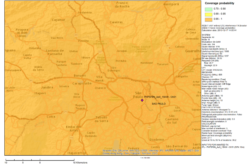
Coverage probability of fixed roof top with 10 meters high antennas with amplifiers without LTE Downlink interference
The image above represents a coverage map that did not take into account, interference from LTE. The images below illustrates the impact to ISDB-T network coverage if 700MHz will be freed for used by mobile services/LTE.
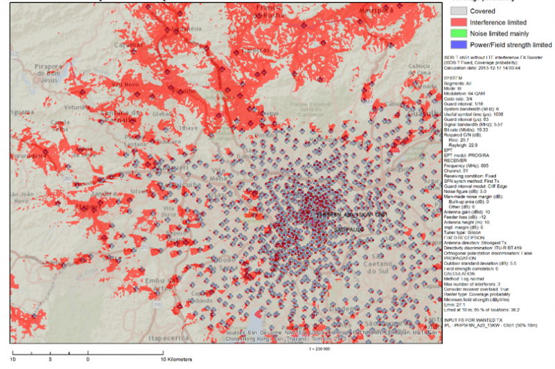
Coverage map of fixed rooftop from 10 meters high antennas with amplifier, when LTE downlink interference is present. Interference is higher at the edges of the coverage area, this is mainly caused by insufficient protection ratios.
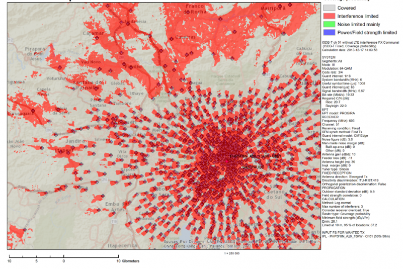
When simulation was performed with receiving characteristics of fixed rooftop with communal antenna at 30 meters antenna height and booster, the downlink interference grew considerably. It potentially affects service reception by over 40% of the population.
Recommended Strategy for Mitigation:
Downlink – Reducing Interference form LTE base stations
- Adding filters
The MCL calculations showed that receiver overload is the critical problem for creating interference to the rooftop antennas using amplifiers. In these cases, there is a need for additional receiver filtering. Since it’s not possible to insert a filter before antennas with integrated amplification, we recommend their replacements. As the Oth values presented in the measurements are not significantly improved with a broader frequency difference, there will be a need for filters even when lower UHF channels are used for DTT.
- Adjusting OOB requirements, improving ACS
We recommended imposing stricter OOB requirements for the LTE base stations, in particular, in built-up areas. Besides, there is also a need to enhance the ISDB-T receiver’s ACS. Due to the large guard band between the LTE downlink and DTT (60 MHz), this would be easy to achieve with the presence of additional external filtering. We projected that the cost for making such adjustments to each base station would be small.
- Positioning
LTE base stations will require very high receiver filter attenuation in combination with stringent OOB emission limits. Therefore, we recommend positioning LTE Base station on the same roof as the DTT antenna to minimize interference imposed on communal rooftop antenna receptions.
- Specific Recommendations for Communal rooftop antennas
Mitigation for interference created for communal rooftop antennas is imperative since they suffer the most significant loss in reception. If LTE Base stations are to be positioned on the same roof as the DTT antenna, they will require very high receiver filter attenuation in combination. We will then be able to mitigate interference more effectively with the combination of stringent OOB emission limits for the LTE base station.
Downlink – Reducing Interference form LTE base stations
- Increase OOB emission limits
To minimize the interference from the LTE uplink, OOB emission limits from the LTE terminals need to increase by about 25-30 dB, when compared to the 3GPP specification at that time. An OOB emission limit of about ‑50 to ‑55 dBm / 6 MHz would be desirable.
- Improving ACS
We recommend improvements in ACS of ISDB-T receivers. This can be achieved by inserting external filters in legacy receivers, allowing a gain of about 20 dB. For future receivers, which might not have the 700 MHz band within its tuning range, it should be possible to improve the ACS further if needed. Care should be taken with the usage of external filters to avoid imposing excessive attenuation to channel 51 (692-698 MHz), which would have the coverage area reduced.
Caution:
Even when all the above recommendations were to be implemented, the usage of indoor DTT receiving antenna as an LTE terminal will be limited. Hence, indoor antennas would need to be replaced by outdoor antennas.
Furthermore, most of the 1seg receivers, such as mobile phones, vehicle GPS units, USB receivers and other portable devices used for portable/mobile ISDB-T reception, have built-in antennas, so it won’t be possible to insert external filters to these devices. They should be replaced by newer ones, manufactured with an integrated receiving filter, in order to mitigate the interference they would suffer from LTE transmissions. It seems particularly challenging to manufacture APT 700 MHz LTE mobile phones with 1seg receiving feature without being self-interfered.
Impact:
From the studies conducted, we were able to provide our clients with a clearer picture on the extent of their challenge, and the mitigation strategy when 700 MHz band (698-806 MHz) would be released for use by LTE mobile services. Our client were able to used the results from this study to support their follow-up actions, and ensure continuity in delivering high-quality services throughout the country.
Capture the values and resolve issues from the Digital Dividend in the right way!